E1 Comprehensive Usage Document
I.About E1
(I)Component Information
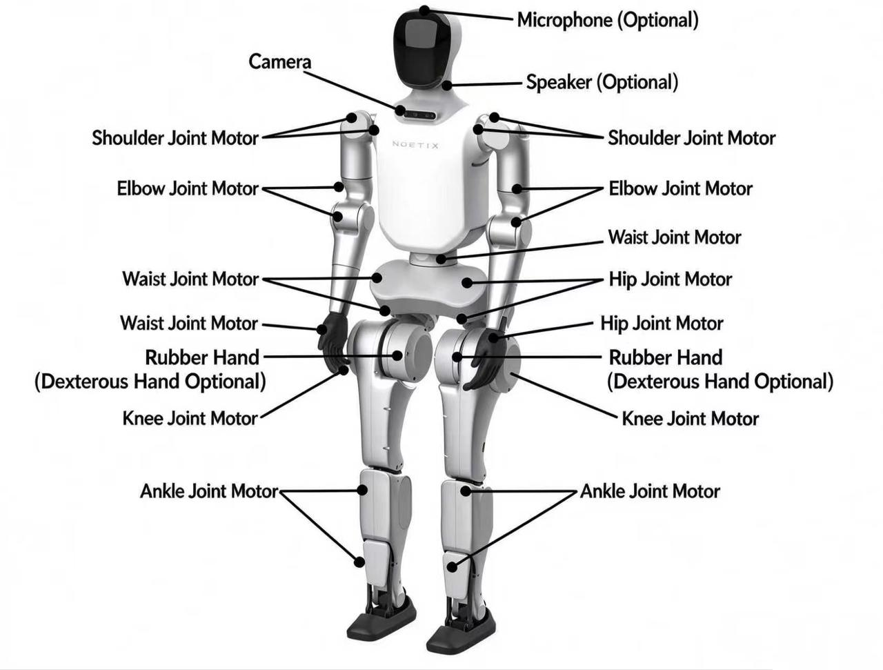
E1 consists of an upper body and a lower body, with 23 degrees of freedom (DoF) in total. Each arm has 5 DoF, including (right-handed coordinate system):
Shoulder joint pitchShoulder joint rollUpper arm joint yawElbow joint pitchLower arm joint yaw
Each leg has 6 DoF, including:
Hip joint yawHip joint rollHip joint pitchKnee joint pitchAnkle joint pitchAnkle joint roll
The waist joint has 1 DoF, including:
Waist joint yaw
Equipped with multiple joint motor degrees of freedom, the E1 robot is capable of achieving precise motion control and attitude control.
Details are as follows:
 |  |
|---|---|
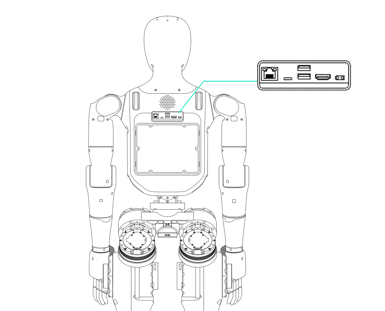
| Front View | Rear View |
| Parameter | E1 | E1 — Education Edition |
|---|---|---|
| Height, Width and Thickness (Standing) | 1400mm*485mm*320mm | 1400mm*485mm*320mm |
| Weight with battery | Approx. 40 kg | Approx. 40 kg |
| Total DoF | 23~28 | 23~28 |
| DoF per leg | 6 DoF | 6 DoF |
| DoF per arm | 5 DoF | 5 DoF |
| Waist DoF | 1 DoF | 1 DoF |
| Computing module | / | Jetson Orin Nano Super |
| Joint communication | Ethercat & Canfd | Ethercat & Canfd |
| Joint motor communication baud rate | 1M | 1M |
| Maximum joint torque | 150N.m | 150N.m |
| Lower-leg & thigh length | Approx. 700 mm | Approx. 700 mm |
| Arm span | Approx. 600 mm | Approx. 600 mm |
| Joint encoder | Dual encoder | Dual encoder |
| Cooling System | Local Air Cooling | Local Air Cooling |
| Power supply | Lithium battery | Lithium battery |
| Base computing power | 6Tops | 6+67Tops |
| Perception sensors | IMU, depth camera | IMU, depth camera |
| Microphone array | Standard configuration | Standard configuration |
| Speaker | Standard configuration | Standard configuration |
| Camera model | DC_V93 | RealSense D435I |
| Smart battery | Quick-release battery, 48 V 10.5 Ah | Quick-release battery, 48 V 10.5 Ah |
| Charger | Yes | Yes |
| Remote controller | Yes | Yes |
| Battery life | 3~4H | 3~4H |
| Secondary development | / | Yes |
(II)Electrical Interface
The following electrical interfaces are provided on the rear of E1:
| Type | Quantity |
|---|---|
| RJ45 | 1 |
| USB | 2 |
| Type-C | 1 |
| HDMI | 1 |
| XT30 external power output 12 V (Max 5 A) | 1 |
The HDMI port is connected to themotion control board (RK3588S).If you have purchased the Education Edition, thecomputing board (NVIDIA Jetson Orin Nano Super)can currently only be accessed via SSH.
(III)Airborne Computer
| Type | Model | User | Password | IP | Computing power | Frequency | Memory |
|---|---|---|---|---|---|---|---|
| Motion Control Board | Rockchip RK3588S | The motion control board is not open to users | The motion control board is not open to users | 192.168.55.102 | 6 Tops | 2.4GHz | 8+64GB |
| Secondary Development Computing Board | NVIDIA Jetson orin nano super | noetix | e1 | 192.168.55.101 | 67 Tops | 1.7GHz | 8+128GB |
The secondary development computing board is available only on the Education Edition of E1.
The Motion Control Board (Rockchip RK3576) is not accessible to users. If the user accesses the Motion Control Board without authorization and this causes the robot’s motion control program to malfunction or lose control, our company shall not be responsible for any resulting damage or losses.
(IV)Camera Information
Intel® RealSense™ Depth Camera D435i - Product Specifications | Intel
(V) Battery Information
| Parameter | Information |
|---|---|
| Brand | Shenzhen Grepow |
| Model | GRP7865125-13S1P |
| Capacity | 10.6Ah |
| Voltage | 48V |
II.Instructions for Use
(I) Operating Procedure and Precautions
The E1 robot should always be secured with a protective bracket during routine demonstrations, especially during secondary development, to ensure safe operation and prevent damage to the robot.
The factory motion control functions do not currently support climbing up or down stairs. Please operate the E1 robot on flat, open ground and keep it away from crowds to avoid injury or damage caused by a fall.
Operating Procedure
Remove the robot from the packaging box. It is suggested to lift the robot onto a bracket and power it on, or place it lying on the ground to start it.
Install the battery
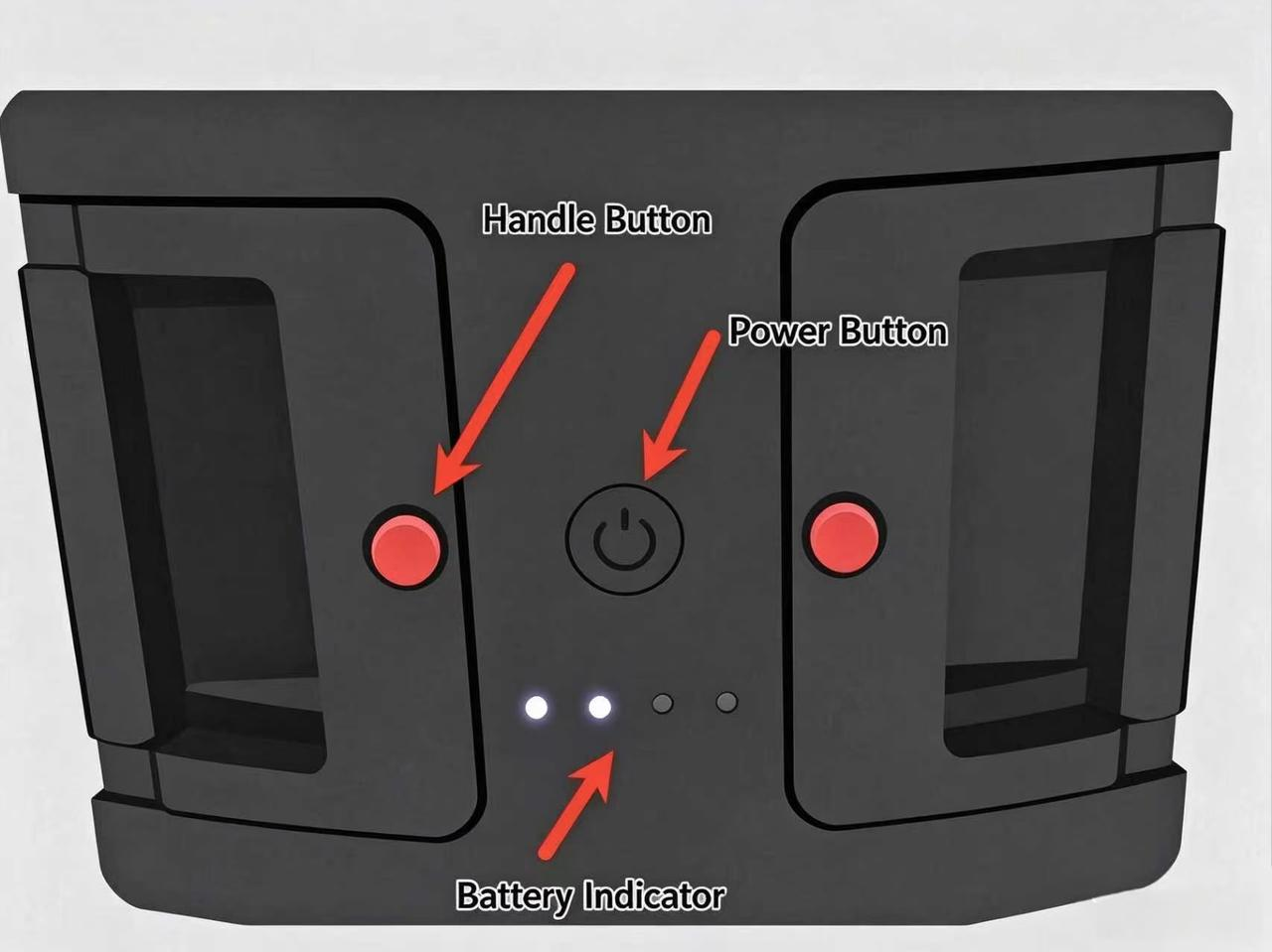
At the same time, press the red button on the handle of the battery and lift the handle. Put the battery into the battery compartment (the battery indicator light is at the bottom). After fully inserting the battery (the clip is securely fastened), press the red button on the handle to lower the handle and lock the battery.
Precautions:When installing the battery, pay attention to orientation. The button is on top and the indicator light is at the bottom. (Refer to the battery diagram below)
Install the controller receiver
Insert the controller USB receiver into any USB port on the rear of the robot and ensure that the connection is firm with no looseness.
Start the robot
After inserting the battery into the rear of the robot, first short-press the power button on the battery. Once the indicator lights up, press and hold the button. A flowing-light effect will be displayed, and observe that the indicator lights on each part of the robot turn on, indicating that power-on is complete.
Pair the handle
If this is the first time pairing the handle with the receiver, the robot must already be powered on with the handle receiver inserted. Press and hold the Home button on the handle until the indicator stays on steadily, then release it. The indicator will start flashing rapidly to enter pairing mode. When the handle vibrates and the three indicators below remain steadily on, pairing is successful. Once pairing is complete, you can directly press the Home button to reconnect using the saved pairing in subsequent uses. The following operations are described using the Aolion controller as an example.
Enter Walking Mode
After the robot is powered on, wait about 10 seconds and it will automatically enter Enabled Mode (Damping Mode).
After the robot enters Enabled Mode, stand it upright on the floor and press LB & - to enter Preparation Mode.
Observe whether the robot's legs are slightly bent. Once this occurs, press LB & X to enter Walking Mode. If the legs are not bent, repeat the previous step.
Note: Robots cannot climb stairs higher than 5 cm or overcome obstacles. They also cannot walk on slopes with an angle greater than 20 degrees (there is a risk of falling).
For subsequent operations, refer to the button function table below.
For subsequent operations, refer to the flow diagram and the button function table below.
Power-off Procedure
After use, hold the robot and press LB & - to return it to Preparation Mode. At this point the robot loses the ability to stand on its own and must be held by the user.
After hanging the robot or laying it flat (on its back), press the + key to put the robot into the disabled mode.
Then press and hold the motor switch. After the robot is powered off, remove the battery.
Operating flow diagram:
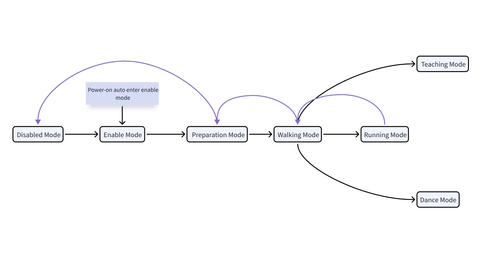
- The black left-pointing arrow indicates the normal power-off flow.
- The purple right-pointing arrow indicates the normal operating flow.
- Pressing the Emergency Stop button
(+)from any mode other than Disabled Mode will force the robot into Disabled Mode. Be careful to avoid accidental activation during use.
Handle Button Function Table
- Basic Functions
| Precondition | Button Combination | Function | Note |
|---|---|---|---|
| Disabled / Enabled Mode | + | Enable / Disable | After the robot is powered on, it automatically enters Enabled Mode. No need to press this when not performing a shutdown operation. |
| Enabled Mode | LB & - | Bent-leg Preparation Mode | At this point the robot cannot balance autonomously and must be held in a standing position. |
| Preparation Mode | LB & X | Walking Mode | After executing a hand action, entering Walking Mode resets the action. |
| Walking Mode | A | Preset Handshake Action | Re-enter Walking Mode to reset. |
| Walking Mode | B | Preset Greeting Action | Re-enter Walking Mode to reset. |
| Walking Mode | Y | Preset Cheer Action | Re-enter Walking Mode to reset. |
| Walking Mode | LB & Y | Running Mode | Please reserve sufficient space and an advance stopping distance of about 1 meter. |
| Walking / Running Mode | 左摇杆 | Move forward / backward | |
| Walking / Running Mode | 右摇杆 | Turn left / right |
The + button on the Aolion controller is used to enable/disable the robot and can also serve as an emergency stop.
During normal operation, do not press or accidentally activate the + button, otherwise the robot will be immediately disabled and may fall to the ground, which may result in damage.
Controller Button Function Diagram
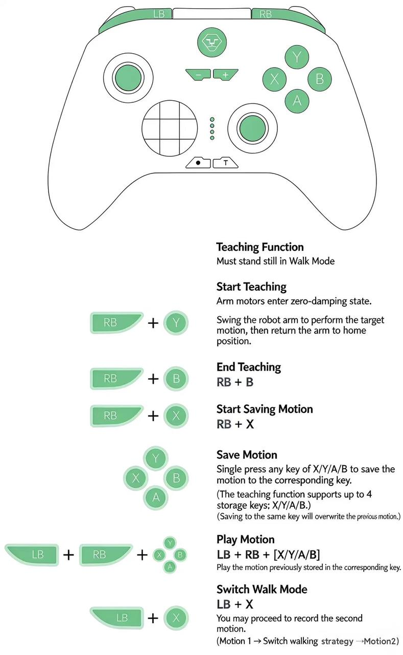
The button functions shown below are independent and do not have any order or sequence.
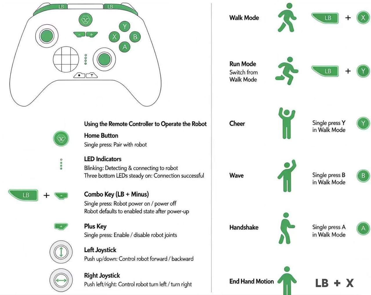
- Teaching Function
Button Combination | Precondition | Function | Note |
|---|---|---|---|
RB & Y | Walking Mode | Enter Teaching State | |
RB & B | Teaching State | End Teaching | |
RB & X | Teaching Ended | Save Teaching | Then press [A, B, X, Y] to save to the corresponding button. |
RB & LB + \[A, B, X, Y\] | Walking Mode | Play the teaching action saved to the corresponding button | After playback, switch back to Walking Mode. |
- Dance Function
When using the Dance function, please observe the following precautions:
- Reserve a sufficiently large activity space as specified in the remarks, and ensure the floor is flat and non-slip.
- Battery level must be at least 2 bars.
- During dancing, do not pull the robot with force, and prevent the robot from being disturbed by external forces.
- Some dances can be interrupted partway by switching to Walking Mode when close to the standing pose, but do not switch to Walking Mode while the robot is performing a bending motion. PS: Avoid using the dance function on slippery surfaces or on uneven ground; provide sufficient room for the robot to perform its motions. Damage to the robot caused by the operating environment or operator errors is not covered by the warranty.
If you wish to test the dance function after receiving the robot, the first test must be supervised by a person. Hold a safety rope (used for protection only — do not apply additional force to the hanging rope) and reserve a sufficiently large demonstration space, so that you can clearly understand the required working space before conducting subsequent demonstrations. If a problem occurs during the first test, please contact customer service promptly.
| Button Combination | Precondition | Function | Note |
|---|---|---|---|
LB & B | Walking Mode | Play Tai Chi motion (unstable, currently unavailable) | Please reserve a 6 × 6 (m) space. |
Joystick Drift:
If the controller buttons drift or become unresponsive, please refer to the official user manual to perform a reset or calibration to ensure normal functionality (please unplug the receiver before performing the operation): : https://mp.weixin.qq.com/s/cL3EBsndt2_ChM5iNgraSQ(Under normal circumstances, this manual is not required.)
Precautions:When the controller appears unresponsive, please contact technical support first to determine whether the issue is with the robot or with the controller.
(II) Joint Motor Information
The joint motor status data of the E1 robot is obtained through the SDK interface. The returned order is fixed, as follows:
| ID | Name | Joint | Torque | Angle Range | Radian Range |
|---|---|---|---|---|---|
| 0 | arm_l1_joint | Left arm shoulder pitch joint | 27N.m | [-163, 163] | [-2.84, 2.84] |
| 1 | arm_l2_joint | Left arm shoulder roll joint | 27N.m | [0, 135] | [0, 2.36] |
| 2 | arm_l3_joint | Left upper-arm yaw joint | 27N.m | [-150, 150] | [-2.62, 2.62] |
| 3 | arm_l4_joint | Left arm elbow pitch joint | 27N.m | [-130, 10] | [-2.27, 0.17] |
| 4 | arm_l5_joint | Left lower-arm yaw joint | 27N.m | [-160, 160] | [-2.79, 2.79] |
| 5 | leg_l1_joint | Left leg hip yaw joint | 90N.m | [-40, 53] | [-0.70, 0.92] |
| 6 | leg_l2_joint | Left leg hip roll joint | 90N.m | [-40, 35] | [-0.70, 0.61] |
| 7 | leg_l3_joint | Left leg thigh pitch joint | 150N.m | [-85, 50] | [-1.48, 0.87] |
| 8 | leg_l4_joint | Left leg knee pitch joint | 150N.m | [0, 135] | [0, 2.36] |
| 9 | leg_l5_joint | Left leg ankle pitch joint | 70N.m | [-58, 24] | [-1.01, 0.42] |
| 10 | leg_l6_joint | Left leg ankle roll joint | 70N.m | [-90, 90] | [-1.57, 1.57] |
| 11 | arm_r1_joint | Right arm shoulder pitch joint | 27N.m | [-163, 163] | [-2.84, 2.84] |
| 12 | arm_r2_joint | Right arm shoulder roll joint | 27N.m | [-135, 0] | [-2.36, 0] |
| 13 | arm_r3_joint | Right upper-arm yaw joint | 27N.m | [-150, 150] | [-2.62, 2.62] |
| 14 | arm_r4_joint | Right arm elbow pitch joint | 27N.m | [-130, 10] | [-2.27, 0.17] |
| 15 | arm_l5_joint | Right lower-arm yaw joint | 27N.m | [-160, 160] | [-2.79, 2.79] |
| 16 | leg_r1_joint | Right leg hip yaw joint | 90N.m | [-53, 40] | [40, 0.70] |
| 17 | leg_r2_joint | Right leg hip roll joint | 90N.m | [-35, 40] | [-0.61, 0.70] |
| 18 | leg_r3_joint | Right leg thigh pitch joint | 150N.m | [-85, 50] | [-1.48, 0.87] |
| 19 | leg_r4_joint | Right leg knee pitch joint | 150N.m | [0, 135] | [0, 2.36] |
| 20 | leg_r5_joint | Right leg ankle pitch joint | 70N.m | [-58, 24] | [-1.01, 0.42] |
| 21 | leg_r6_joint | Right leg ankle roll joint | 70N.m | [-15, 15] | [-0.26, 0.26] |
| 22 | waist_1_joint | Waist yaw joint | 70N.m | [-90, 90] | [-1.57, 1.57] |
(III) Controller Button Data Mapping
| Button Description | Button index |
|---|---|
| Right shoulder button | 1 |
| Left shoulder button | 2 |
| X | 5 |
| Y | 6 |
| B | 7 |
| A | 8 |
| + | 9 |
| - | 10 |
| None | 11 |
| Left joystick pressed | 12 |
Controller Joystick Data Range
| Minimum value | Maximum value |
|---|---|
| -1 | 1 |
(IV) Video Tutorials
- Operating Tutorial
- Packaging Tutorial
III. E1 Development Guide
Introduction to SDK
This document describes the development of E1 based on the DDS message middleware for communication. This SDK adopts a C/S architecture, under which a DDS client program deployed on the secondary-development computing board of the E1 robot and the motion control program running on the motion control board (acting as the server) issue control commands at a frequency of500 Hz and continuously obtain the current robot status. The DDS adopted is CYCLONEDDS 0.11.0.
Note:
Only E1 units equipped with a computing board can use this SDK for development.
(I) System Architecture Diagram
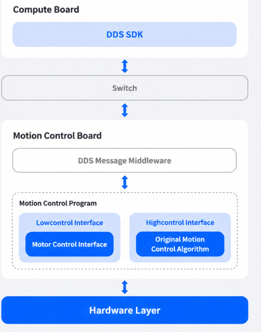
(II) Development Interfaces
DDS C++ Python
(III) Obtaining the SDK
https://github.com/Noetix-Robotics/noetix_sdk_e1
(IV) URDF Files
Please log in to the Noetix Robotics after-sales platform to download.
(V) Voice Interaction Function
Voice interaction function:the robot head equipped with voice interaction features a ring-shaped 6-microphone pickup array, an AI sound card, and a speaker. The audio format is stereo (2 channels), with a sampling rate of 16 kHz and a sample depth of 16 bits. It also integrates the iFLYTEK AI large model (iFLYTEK Spark 4.0 Ultra) for Q&A capabilities. Wake word: "Hello Xiao E". Wake-up range within 3 m. Sleep wait time 30 s. The main controller has a built-in operator-dedicated 4G SIM card with 100 GB of monthly data. Network service is provided for one year from the date of factory activation. Precautions: The voice module uses an operator-provided IoT SIM card. By default, it provides one year of data service from the date of activation. Subsequent use requires the customer to purchase their own data plan. Our company provides the SIM card number and the necessary technical support. The customer shall be solely responsible for any consequences resulting from SIM card damage or misuse. Our company shall not be liable for network connection failures or other issues caused by the operator during use.
Voice SDK Description
Voice wake word: "Hello Xiao E". Say "I am here" after the wake word to start a Q&A session. Voice secondary development (this manual is limited to the Education Edition): https://noetixrobotics.feishu.cn/wiki/M6gkwQMXji9jEFkK8uvcIYLHnfd https://noetixrobotics.feishu.cn/docx/BdJddzSwqoDhd9xixobcXj9XnAe Precautions: Self-registered AIUI platform applications have a limited number of interaction requests.
(VI) Application Development — HighController
Introduction to Application Development HighController is intended for upper-layer scheduling development built on top of the OEM motion control strategy. Without modifying the underlying control logic, it enables rapid construction of robot automation applications and supports integration with large language models to build customized intelligent behavior systems. Typical applications include:
- Combining visual algorithms with the OEM motion control system to achieve autonomous perception and autonomous navigation.
- Integrating with the voice interaction module to achieve natural-language control.
- Connecting with a large language model to dynamically generate and invoke OEM control actions based on input (carries certain risks and requires strict security policies).
- Working with an external perception radar to implement positioning, navigation, and inspection systems.
In short, HighController encapsulates the OEM control capabilities through high-level scheduling, enabling automated and programmatic invocation of the behaviors controllable via the remote controller or App, while extending these with selected autonomous and intelligent capabilities.
1. HighController Architecture Diagram
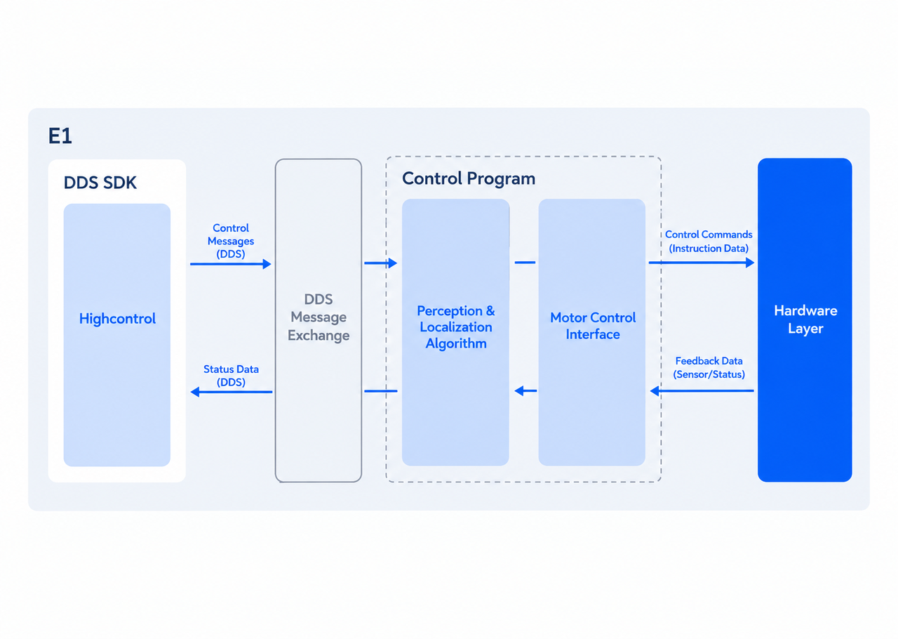
(1) Status Reporting Mechanism
After the Client SDK establishes a connection with the robot motion control program, the motion control program will continuously send real-time robot status information to the Client, including:
- Whole-body motor parameter data (
pos (position),vel (velocity),tau (torque),kp,kd,temperature,error) - IMU status data
- Current working mode (
workmode, indicating the currently running control strategy) - Aolion Controller Data (for Synchronized Manual Input or Auxiliary Control)
- Battery level and related system status information
(2) Client Control Command Issuance
The Client, based on its own application scenarios, sends control commands to the operation and control program, which mainly include:
- (x, y, z) movement control data is only valid in specific modes, such as walking mode, handshake, greeting, cheering, teaching mode, etc.
- action command
corresponds to
workmode, which is used to switch or trigger the algorithm strategy currently running on the robot. - data additional DDS data
PLAYTEACH(playback teaching mode), and is used to specify additional parameters such as the teaching file index.
(3) Internal processing flow of the operation control program
After receiving the client's instructions, the control program:
- Transfers the control parameters to the internal control algorithm
- The algorithm calculates the strategy based on the reinforcement learning model
- Generate the target expected values (target position, velocity or torque) of the motor and send them to the motor control interface
- Deliver the calculation results to the hardware control layer
(4) Hardware Execution Layer
After the hardware layer receives the target control data, it:
- Executes the motor control commands.
- Performs the corresponding desired action.
Throughout the entire process, users only need to issue a portion of high-level control parameters. The specific motion planning, dynamic balance and motor-level control calculations are all completed by the Black Box Algorithm in the original manufacturer's motion control program. Therefore, in HighController mode, the range of capabilities that users can invoke and automate is, in principle, limited to the functional boundaries originally achievable by the APP or the controller, without granting underlying motor-level control access.
2.HighController Operation Flowchart
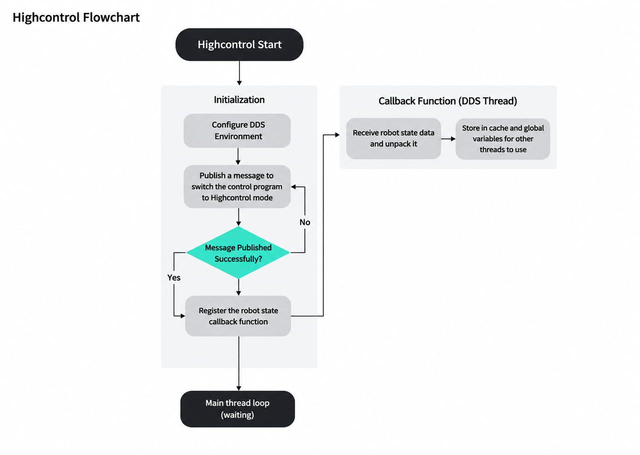
(1) Initialization Phase (init)
After the system starts, the following initialization procedure is completed:
- Establish a communication connection between the client and the robot motion control program.
- Register the callback function for receiving robot status data.
(2) Status Data Callback Mechanism
The motion control program continuously pushes robot status data to the client. After the callback function receives the data, it encapsulates it and stores it in the corresponding buffer and global state variable:
motor_state_buffer_:motor status bufferimu_buffer_: IMU status bufferjoy_buffer_:controller data buffercurmode:current motion control strategy mode (global variable) This stage only handles data reception and caching; it does not perform control decision computations.
3. HighController Parameters and Common Interfaces
| Interface Name | Interface Description | Return Type |
|---|---|---|
| instance | Obtain the singleton pointer of HighController | Object pointer |
| init | Initialize the HighController object | None |
| publish_cmd | Publish DDS control command data | None |
| subscribe_robot_hardware_status | Subscribe to robot hardware status information | None |
| subscribe_robot_hand_status | Subscribe to dexterous-hand status information (callback takes a byte stream) | None |
| publish_hand_data | Send control data to the dexterous hand (byte stream) | None |
Obtain the singleton instance of the HighController object
| Function Name | instance |
|---|---|
| Function Prototype | static HighController *Instance() |
| Function Overview | Obtain the HighController singleton. |
| Parameters | None |
| Return Value | Pointer to the HighController singleton object |
| Note |
C++Example:
HighController *ctrl = HighController::Instance();
PythonExample:
ctrl = HighController.instance()
HighController Object Initialization
| Function Name | init |
|---|---|
| Function Prototype | bool init() |
| Function Overview | Initialize the HighController object. |
| Parameters | None |
| Return Value | bool |
| Note |
C++Example:
ctrl->init();
PythonExample:
ctrl.init()
Publish Robot Control Commands
| Function Name | publish_cmd |
|---|---|
| Function Prototype | void publish_cmd(double ver, double hor, double yaw, ControlCmd action, uint16_t index) |
| Function Overview | Send a DDS control command via HighController. |
| Parameters | • ver range:[-1, 1];longitudinal motion value (> 0 forward) • hor range:[-1, 1];steering value (> 0 turns left) • action: robot mode-switching enumeration • index: specified index for teaching-related modes |
| Return Value | 无 |
| Note | This interface cannot be called continuously; otherwise, the robot will receive commands too quickly and fail to respond. Add a delay of at least 2 ms between consecutive commands. |
C++Example:
ctrl->publish_cmd(0, 0, ControlCmd.CHEER, 0);
PythonExample:
ctrl.publish_cmd(0, 0, ControlCmd.CHEER, 0)
actionThe parameter indicates switching the robot to the corresponding mode
| Parameter Name | Definition Prototype | serial number | Example Value | Description (Corresponding Button in Parentheses) |
|---|---|---|---|---|
ControlCmd | | 0 | WALK | Walking Mode (LB & X) |
| 1 | SWING | Factory-preset action: Wave(B) | ||
| 2 | SHAKE | Factory-preset action: Handshake (A) | ||
| 3 | CHEER | Factory-preset action: Cheer (Y) | ||
| 4 | RUN | Running Mode (LB & Y) | ||
| 5 | START | Enable / Disable (Emergency Stop, +) | ||
| 6 | SWITCH | Preparation Mode (LB & -) | ||
| 7 | STARTTEACH | Start Teaching (RB & Y) | ||
| 8 | SAVETEACH | Save Teaching
PS: Currently, sending SAVETEACH will first send ENDTEACH and then SAVETEACH, equivalent to combining the two steps into one.
The saved file is determined by the file_index parameter; please refer to the HighController::set_axes interface for details. | ||
| 9 | ENDTEACH | End Teaching (RB & B) | ||
| 10 | PLAYTEACH | Play Teaching (file_index)
Plays the corresponding teaching file according to file_index. | ||
| 11 | DEFAULT | Null command |
Purpose of the DEFAULT Null Mode
And the process control function runs periodically. If teaching-related commands such as action = ControlCmd:: PLAYTEACH;are continuously issued within this loop, the robot may repeatedly interrupt the teaching playback action before it has finished, causing the robot to appear stuck and unresponsive.
Correct Practice
PLAYTEACH is a one-time trigger instruction (event) and shall only be sent once; afterward, continuously send DEFAULT (a no-op command) in the loop to prevent repeated triggering.
Sample Code (Revised)
if (is_first) {
    action = ControlCmd::CHEER;  // Triggered only once
    is_first = false;
} else {
    action = ControlCmd::DEFAULT;
}
Effect
- Received
PLAYTEACH→ Trigger and fully execute the teaching action - Subsequent
DEFAULT→ No longer interrupts the action - The robot behaves normally and predictably Action commands shall be "edge-triggered" and must not be continuously issued within a control loop.
indexis used to specify the teaching file index in teaching-related modes
ctrl.publish_cmd(0, 0, ControlCmd.STARTTEACH, 0)  # Start teaching
sleep(10)  # Record the teaching action
ctrl.publish_cmd(0, 0, ControlCmd.SAVETEACH, 1)  # End and save the teaching action with index 1
sleep(2)  # Let the motion control program complete the save process to prevent interruption by the next command
ctrl.publish_cmd(0, 0, ControlCmd.PLAYTEACH, 1)  # Play teaching file 1
Only when action is one of the following modes:
PLAYTEACH / WALK / SWING / CHEER / SHAKE / DEFAULT
x and yaw will take effect to control the robot's movement; in other modes,x and yaw are invalid.
Subscribe to hardware status information of the robot
| Function Name | subscribe_robot_hardware_status |
|---|---|
| Function Prototype | void subscribe_robot_hardware_status(RobotHardwareStatusCallback callback); |
| Function Overview | Subscribe to robot hardware status information. |
| Parameters | - callback: callback function for processing robot status data |
| Return Value | None |
| Note |
C++Example:
ctrl->subscribe_robot_hardware_status(
    [](const RobotHardwareStatus &status) {
    latest_hw_status = status;
});
Python Example:
def _on_hw_status(status):
    global latest_hw_status
    atest_hw_status = status

ctrl.subscribe_robot_hardware_status(_on_hw_status)
| Parameter Name | Definition Prototype | Parameter | Description |
|---|---|---|---|
| RobotHardwareStatus | | imu_data | IMU data |
| remote_data | Controller data | ||
| motor_data | Motor data | ||
| workmode | Current working mode |
workmodeParameter Correspondence Table
| workmode Value | Description |
|---|---|
| 0 | Enabled Mode |
| 1 | Preparation Mode |
| 2 | Walking Mode |
| 3 | Running Mode |
| 7 | Factory-preset action: Greeting |
| 8 | Factory-preset action: Handshake |
| 9 | Factory-preset action: Cheer |
| 10 | Start Teaching |
| 11 | End Teaching |
| 27 | Play Teaching |
| 13 | Save Teaching 1 |
| 28 | Tai Chi motion |
| 26 | Save Teaching 2 |
| 29 | Disabled Mode |
Save Teaching Mode
After the SDK sends a SAVETEACH command to the robot, the robot will sequentially return three statuses: Exit Teaching Save Teaching 1 Save Teaching 2.
Protected Mode Under the standing control strategy (walking, teaching, dancing, etc.), the motion control program continuously monitors the IMU attitude data. When the system detects that the posture deviates from the standing stability range and exceeds the preset threshold, it will immediately trigger the protection mechanism and forcibly switch to the safe mode. In protected mode:
- All joints of the body enter a disabled state (the motor stops active output)
- Terminate the current motion control strategy
- Block the execution of further action instructions The purpose of this mechanism is as follows:
- Prevent the robot from continuously outputting control torque during a fall or instability
- Avoid secondary injury caused by uncontrolled swinging of the limbs
- Mitigate potential damage to the equipment itself and the surrounding environment This protection logic, as a underlying safety protection mechanism, enjoys the highest priority and will not be affected by upper-layer control instructions.
Controller Data Structure
| Parameter Name | Definition Prototype | Example Value | Description |
|---|---|---|---|
| joydata | | axes | Remote control remote sensing linear value |
| button | Remote control button press mapping value: 1 means pressed, 0 means normal |
| Controller Joystick Mapping | Mapping Description | Range |
|---|---|---|
| axes[0] | Right joystick left/right push value | [-1, 1] |
| axes[1] | Left joystick forward/backward push value | [-1, 1] |
IMU Status Data Structure
| Parameter Name | Definition Prototype | Example Value | Description |
|---|---|---|---|
| NingImuData | | ori | Attitude quaternion |
| ori_cov | Attitude covariance | ||
| angular_vel | Angular velocity | ||
| angular_vel_cov | Angular velocity covariance | ||
| linear_acc | Linear acceleration | ||
| linear_acc_cov | Linear acceleration covariance |
Motor Status Data Structure
| Parameter Name | Definition Prototype | Example Value | Description |
|---|---|---|---|
| MotorState | | pos | Motor position |
| vel | Motor speed | ||
| tau | Motor torque | ||
| motor_id | Motor ID | ||
| error | Motor Error Code:
| ||
| temperature | Temperature |
Subscribe to Dexterous-Hand Status
| Function Name | subscribe_robot_hand_status |
|---|---|
| Function Prototype | void subscribe_robot_hand_status(RobotHandStatusCallback callback); |
| Function Overview | Subscribe to dexterous-hand (hand) status information. |
| Parameters | - callback: callback function for processing dexterous-hand status data; the callback argument is a byte stream(const std::vector<uint8_t>&) |
| Return Value | None |
| Remarks | The callback argument is a raw byte stream; refer to the dexterous-hand communication protocol documentation for the detailed protocol structure. |
C++ Example:
ctrl->subscribe_robot_hand_status(
    [](const std::vector<uint8_t> &data) {
        //  data is the dexterous-hand status byte stream
    });
Python Example:
def _on_hand_status(data):
    # data is of type bytes
    pass

ctrl.subscribe_robot_hand_status(_on_hand_status)
Send Control Data to the Dexterous Hand
| Function Name | publish_hand_data |
|---|---|
| Function Prototype | void publish_hand_data(const std::vector<uint8_t> &data); |
| Function Overview | Send control data to the dexterous hand. |
| Parameters | - data: RS-485 telegram sent to the dexterous hand (byte stream) |
| Return Value | 无 |
| Remarks | data is an RS-485 communication telegram; refer to the dexterous-hand 485 communication protocol documentation for the frame format (header / device address / function code / data / checksum, etc.). |
C++ Example:
std::vector<uint8_t> data = {0x01, 0x02, 0x03};
ctrl->publish_hand_data(data);
Python Example:
# Hand data transmission (RS-485 raw byte stream)
data = bytes([0x01, 0x02, 0x03])  # byte string assembled according to the telegram protocol
ctrl.publish_hand_data(data)
4. Operation Control Status Switching Flowchart
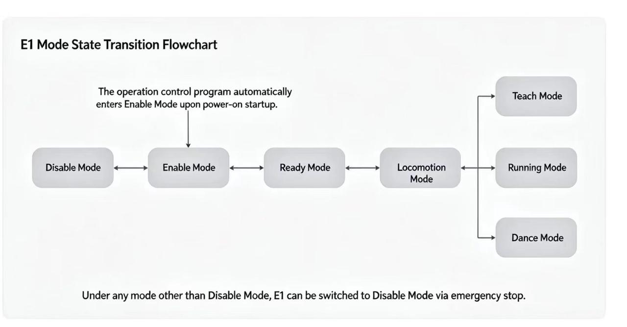
Note:During the development process with HighController, please follow the above flow chart for mode switching to ensure rationality and safety.
5. Introduction to Demo Routines
In the SDK folder, example_high. cpp and test_high. py provide a sample demo, which is used to parse the input data of the Aolion Controller, and generate corresponding control instructions according to the controller operations to send to the robot.
(VI)Operation Control Development - Lowcontrol
Introduction to Operations Control Development Lowcontrol exposes the motor control interface in the motion control program to the SDK, allowing users to directly adjust underlying motor parameters at a control frequency of 500Hz. Combined with the deployment of reinforcement learning algorithms, it enables in-depth customization of E1's motion capabilities, allowing it to complete complex behaviors such as diverse new movements and dances.
1. E1 Training Framework
https://github.com/Noetix-Robotics/noetix_e1_lab.git
2. Lowcontrol Architecture Diagram
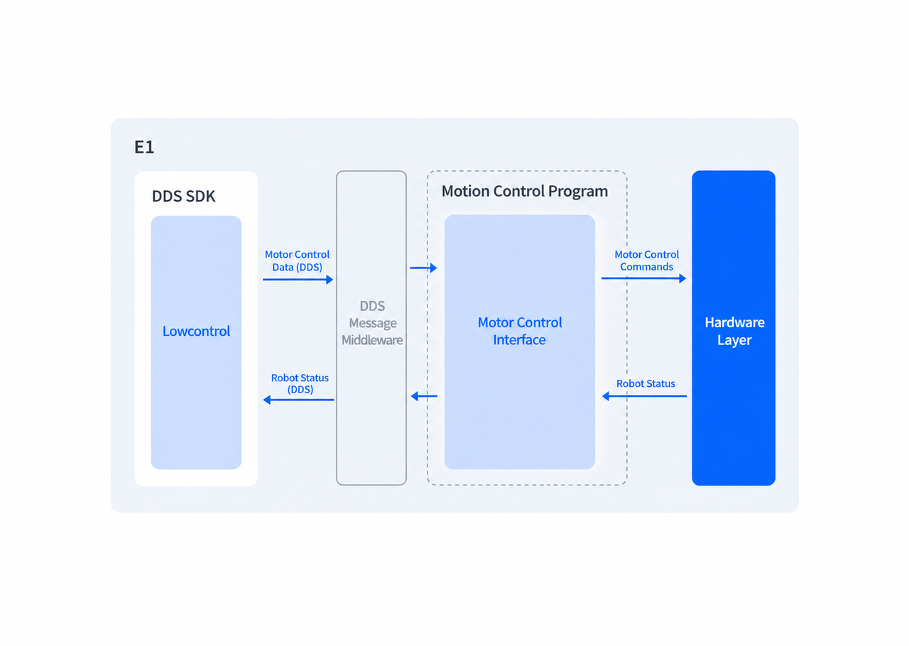
(1) Status Data Reporting
After the client SDK establishes a connection with the robot motion control program, the motion control program continuously pushes real-time robot status information to the client, including:
- Whole-body motor parameter data (pos position, vel velocity, tau torque, kp, kd, temperature, error).
- IMU status data.
- Aolion controller data (for synchronizing manual input or auxiliary control).
(2) Client-side control calculation
The Client, in combination with its own algorithm (usually a reinforcement learning model), performs real-time policy calculation to generate the target expected values (such as target position, etc.) for each motor, writes the motor control instruction array into the buffer, and then delivers it to the motion control program.
(3) Forwarding Mechanism of Operation Control Program
After the operation control program receives the motor command array issued by the Client, it does not perform high-level strategy calculation, but directly forwards the control parameters to the hardware control layer.
(4) Hardware Execution Layer
The hardware layer receives the target parameters of the motor, executes the control commands, and drives the motor to complete the expected actions.
In Lowcontrol mode:
- The reinforcement learning model is deployed on the Client side
- Users can directly participate in motor-level control
- The operation control program is mainly responsible for communication and secure forwarding.
- The control frequency can reach 500Hz This mode features higher control freedom and flexibility, but it also means:
- Higher requirements for algorithm stability.
- Stricter requirements for real-time performance and system security.
- A potential direct impact on robot motion safety if the control strategy is unstable.
3. LowController Operation Flowchart
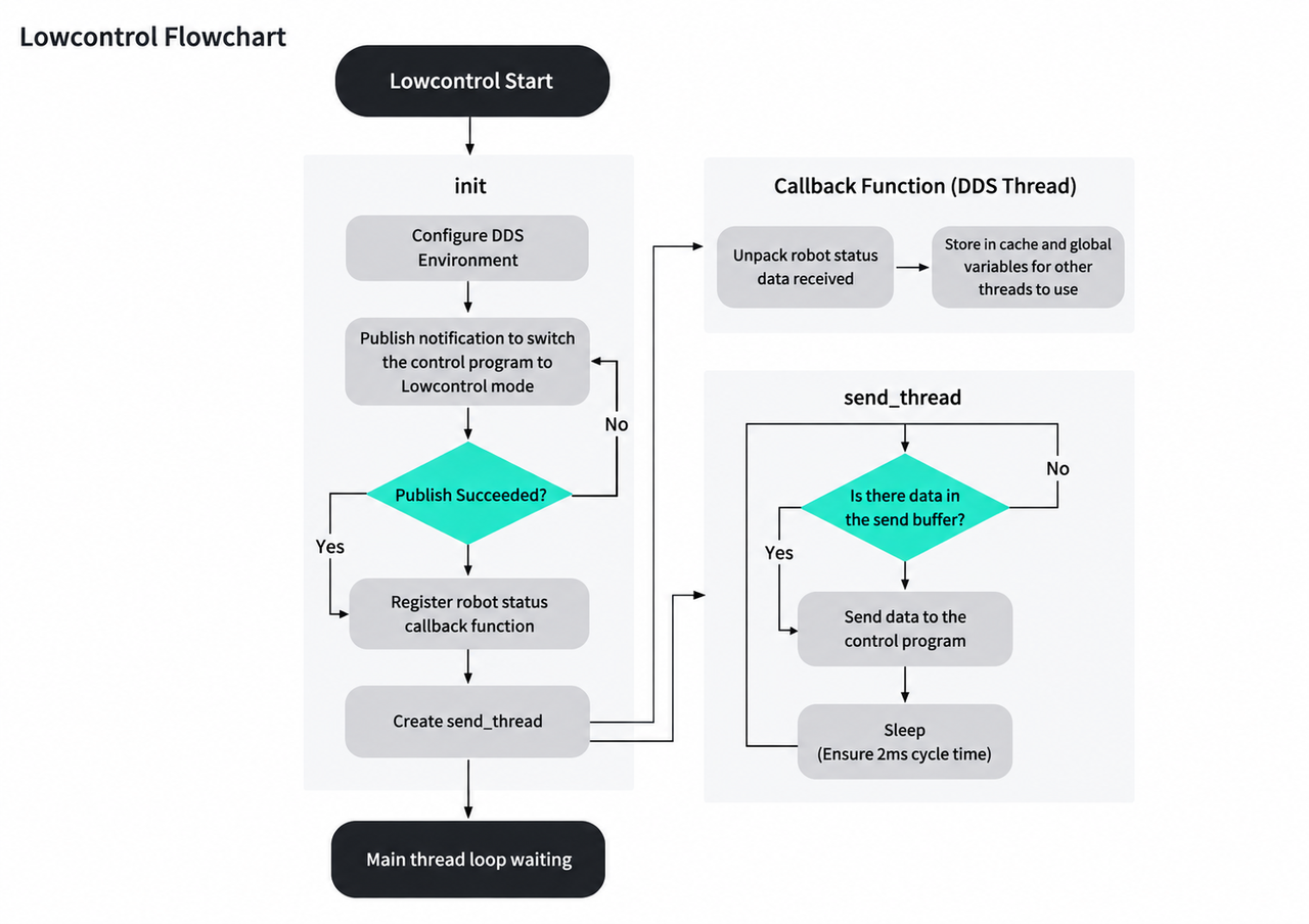
(1)Initialization phase (init)
After the system starts, complete the following initialization steps: a. Establish a communication connection between the Client and the robot operation control program b. Register robot status data receiving callback function c. Create send_thread data transmission thread
(2)Status Data Callback Mechanism
The operation control program continuously pushes robot status data to the Client. After receiving the data, the callback function encapsulates it and stores it in the corresponding buffer or global variable:
motor_state_buffer_:Motor status bufferimu_buffer_:IMU status bufferjoy_buffer_:controller data buffer This stage is only responsible for data reception and caching, and does not participate in control strategy calculation.
(3)send_thread (data transmission thread)
The data transmission thread also operates at a 2 ms cycle:
- If
motor_cmd_buffer_is not empty - Read the latest motor control command
- Send the motor target array to the motion control program The operation control program is only responsible for forwarding data to the hardware layer and does not participate in high-level control decisions.
(4)Architectural Features
The core features of the LowController mode are as follows:
- Client directly participates in motor-level control
- Reinforcement learning or custom control algorithms run on the Client
- The operation control program is no longer responsible for high-level policy calculation, and only undertakes the responsibilities of communication and secure forwarding.
- The control frequency can reach up to 500Hz This model offers higher control freedom and algorithmic plasticity, but at the same time, it imposes requirements on the following aspects:
- Real-time performance
- Algorithm Stability
- Thread Safety and Scheduling Precision
4. 关节电机信息
| ID | Name | Joint | Torque | Angle Range | Radian Range |
|---|---|---|---|---|---|
| 0 | arm_l1_joint | Left arm shoulder pitch joint | 27N.m | [-163, 163] | [-2.84, 2.84] |
| 1 | arm_l2_joint | Left arm shoulder roll joint | 27N.m | [0, 135] | [0, 2.36] |
| 2 | arm_l3_joint | Left upper-arm yaw joint | 27N.m | [-150, 150] | [-2.62, 2.62] |
| 3 | arm_l4_joint | Left arm elbow pitch joint | 27N.m | [-130, 10] | [-2.27, 0.17] |
| 4 | arm_l5_joint | Left lower-arm yaw joint | 27N.m | [-160, 160] | [-2.79, 2.79] |
| 5 | leg_l1_joint | Left leg hip yaw joint | 90N.m | [-40, 53] | [-0.70, 0.92] |
| 6 | leg_l2_joint | Left leg hip roll joint | 90N.m | [-40, 35] | [-0.70, 0.61] |
| 7 | leg_l3_joint | Left leg thigh pitch joint | 150N.m | [-85, 50] | [-1.48, 0.87] |
| 8 | leg_l4_joint | Left leg knee pitch joint | 150N.m | [0, 135] | [0, 2.36] |
| 9 | leg_l5_joint | Left leg ankle pitch joint | 70N.m | [-58, 24] | [-1.01, 0.42] |
| 10 | leg_l6_joint | Left leg ankle roll joint | 70N.m | [-90, 90] | [-1.57, 1.57] |
| 11 | arm_r1_joint | Right arm shoulder pitch joint | 27N.m | [-163, 163] | [-2.84, 2.84] |
| 12 | arm_r2_joint | Right arm shoulder roll joint | 27N.m | [-135, 0] | [-2.36, 0] |
| 13 | arm_r3_joint | Right upper-arm yaw joint | 27N.m | [-150, 150] | [-2.62, 2.62] |
| 14 | arm_r4_joint | Right arm elbow pitch joint | 27N.m | [-130, 10] | [-2.27, 0.17] |
| 15 | arm_l5_joint | Right lower-arm yaw joint | 27N.m | [-160, 160] | [-2.79, 2.79] |
| 16 | leg_r1_joint | Right leg hip yaw joint | 90N.m | [-53, 40] | [40, 0.70] |
| 17 | leg_r2_joint | Right leg hip roll joint | 90N.m | [-35, 40] | [-0.61, 0.70] |
| 18 | leg_r3_joint | Right leg thigh pitch joint | 150N.m | [-85, 50] | [-1.48, 0.87] |
| 19 | leg_r4_joint | Right leg knee pitch joint | 150N.m | [0, 135] | [0, 2.36] |
| 20 | leg_r5_joint | Right leg ankle pitch joint | 70N.m | [-58, 24] | [-1.01, 0.42] |
| 21 | leg_r6_joint | Right leg ankle roll joint | 70N.m | [-15, 15] | [-0.26, 0.26] |
| 22 | waist_1_joint | Waist yaw joint | 70N.m | [-90, 90] | [-1.57, 1.57] |
5. Aolion Controller Data Mapping
Aolion Controller. The button[] and key mapping table are as follows:
| Button Description | Button index |
|---|---|
| Right shoulder button | 1 |
| Left shoulder button | 2 |
| X | 5 |
| Y | 6 |
| B | 7 |
| A | 8 |
| + | 9 |
| - | 10 |
| None | 11 |
| Left joystick pressed | 12 |
| Joystick Mapping | Mapping Description |
|---|---|
| axes[0] | Right Stick Y-Axis Value |
| axes[1] | Left Stick X-axis Value |
Controller Joystick Data Range
| Minimum value | Maximum value |
|---|---|
| -1 | 1 |
6. Common Interfaces and Usage Routines of LowController
| Interface Name | Interface Description | Return Type |
|---|---|---|
| instance | Obtain the singleton pointer of LowController | Object pointer |
| init | Initialize the LowController object | None |
| set_joint | Write the motor control command into the buffer | None |
| getJointsIndex | Obtain the corresponding ID by joint name | int |
| subscribe_robot_hardware_status | Subscribe to robot hardware status information | None |
| subscribe_robot_hand_status | Subscribe to dexterous-hand status information (Callback with byte stream input) | None |
| publish_hand_data | Send control data to the dexterous hand (byte stream) | None |
Obtain the singleton instance of the LowController object
| Function Name | instance |
|---|---|
| Function Prototype | static LowController *Instance() |
| Function Overview | Obtain the LowController singleton |
| Parameters | None |
| Return Value | Pointer to the LowController singleton object |
| Note |
C++ Example:
LowController *ctrl = LowController::Instance();
Python Example:
ctrl = LowController.instance()
LowController Object Initialization
| Function Name | init |
|---|---|
| Function Prototype | bool init() |
| Function Overview | LowController Object Initialization |
| Parameters | None |
| Return Value | bool |
| Note |
C++ Example:
ctrl->init();
Python Example:
ctrl.init()
The array of motor control commands is stored in the buffer.
After being stored in the buffer, the data will be automatically sent by the send_thread thread.
| Function Name | set_joint |
|---|---|
| Function Prototype | void set_joint(std::array<MotorCmd, 24> motorcmd) |
| Function Overview | Set joint data |
| Parameters | - motorcmd motor command structure |
| Return Value | None |
| Note |
| Parameter Name | Define Prototype | Example Value | Description |
|---|---|---|---|
| MotorCmd | | pos | Motor Position |
| vel | Motor speed | ||
| tau | Motor Torque | ||
| kp | pid parameter | ||
| kd | pid parameter | ||
| motor_id | Motor ID |
Please strictly follow the specified parameter range in the Joint Motor Information section when issuing the motor control commands.
C++ Example:
std::array<MotorCmd, 24> motorcmd;
// Algorithm logic omitted ...
ctrl->set_joint(motorcmd);
Python Example:
cmds = [MotorCmd() for _ in range(24)]
# Algorithm logic omitted ...
ctrl.set_joint(cmds)
Obtain the corresponding joint motor ID according to the joint motor name
| Function Name | getJointsIndex |
|---|---|
| Function Prototype | int getJointsIndex(std::string jointname) |
| Function Overview | Obtain the corresponding joint motor ID according to the joint motor name |
| Parameters | jointname: Joint Motor Name |
| Return Value | int:Corresponding joint motor ID |
| Note |
C++ Example:
int id = ctrl->getJointsIndex("arm_l1_joint");
Python Example:
id = ctrl.getJointsIndex("arm_l1_joint");
Subscribe to the hardware status information of the robot
| Function Name | subscribe_robot_hardware_status |
|---|---|
| Function Prototype | void subscribe_robot_hardware_status(RobotHardwareStatusCallback callback); |
| Function Overview | Subscribe to robot hardware status information |
| Parameters | - callback: callback function for processing robot status data |
| Return Value | None |
| Note | The usage is the same as that of HighControllerontroller subscribe_robot_hardware_status |
Subscribe to Dexterous-Hand Status (Same as HighController)
| Function Name | subscribe_robot_hand_status |
|---|---|
| Function Prototype | void subscribe_robot_hand_status(RobotHandStatusCallback callback); |
| Function Overview | Subscribe to dexterous-hand (hand) status information. |
| Parameters | - callback: callback function for processing dexterous-hand status data; the callback argument is a byte stream(const std::vector<uint8_t>&) |
| Return Value | None |
| Remarks | The callback argument is a raw byte stream; refer to the dexterous-hand communication protocol documentation for the detailed protocol structure. |
Send Control Data to the Dexterous Hand (Same as HighController)
| Function Name | publish_hand_data |
|---|---|
| Function Prototype | void publish_hand_data(const std::vector<uint8_t> &data); |
| Function Overview | Send control data to the dexterous hand. |
| Parameters | - data: RS-485 telegram sent to the dexterous hand (byte stream) |
| Return Value | None |
| Remarks | data is an RS-485 communication telegram; refer to the dexterous-hand 485 communication protocol documentation for the frame format (header / device address / function code / data / checksum, etc.). |
Obtain the data of the Aolion Controller
AoLionDriver class
The AoLionDriver Interface
| Interface Name | Interface Description |
|---|---|
| init | Initialization |
| getremotedata | Obtain controller data |
| Function Name | init |
|---|---|
| Function Prototype | bool init(std::string port, int baudrate) |
| Function Overview | Initialize the controller device port |
| Parameters |
|
| Return Value |
|
| Note |
| Function Name | getremotedata |
|---|---|
| function prototype | const joydata getremotedata() |
| Function Overview | Obtain controller data |
| Parameters | None |
| Return Value | joydata: Controller data structure |
| Note |
Usage Examples
C++:
AoLionDriver aoliondriver;
joydata remote_data;
aoliondriver.init("/dev/input/js0", 115200);
const joydata jdata=aoliondriver.getremotedata();
for (int i = 0; i < 14; i++)
    std::cout << jdata.button[i] << std::endl;
std::cout << jdata.axes[0] << std::endl;
std::cout << jdata.axes[1] << std::endl;
Python:
al = AoLionDriver()
al.init("/dev/input/js0", 115200)
jdata = al.getremotedata()
for i in range(14):
    print(jdata.button[i])
print(jdata.axes[0])
print(jdata.axes[1])
7. Introduction to Demo Routines
examples_cpp/example_low.cppruns an E1 24 degrees of freedom walking strategy (policy/policy.onnx)of the sim2real (algorithm model real machine deployment) code. according to the policy provides some reinforcement learning deployment interface
| Function Name | loadModel |
|---|---|
| Function Prototype | bool loadModel(std::string modelpath) |
| Function Overview | Load custom models |
| Parameters | - modelpath: model path |
| Return Value | true: Load succeeded; false: Load failed |
| Note |
| Function Name | onnxdatainit |
|---|---|
| Function Prototype | void onnxdatainit() |
| Function Overview | Initialize onnx data |
| Parameters | None |
| Return Value | None |
| Note |
| Function Name | getmodelparam |
|---|---|
| Function Prototype | bool getmodelparam() |
| Function Overview | Obtain model parameters from the yaml file |
| Parameters | None |
| Return Value | true: YAML file read successfully; false: Failed to read YAML file |
| Note |
| Function Name | setparameter |
|---|---|
| Function Prototype | void setparameter(Command &cmd,bool* isfirst) |
| Function Overview | Set the overall control parameters of the xyz unit |
| Parameters | • cmd:set command • isfirst:Indicates whether this is the first configuration |
| Return Value | 无 |
| Note |
| Function Name | updatestateestimation |
|---|---|
| Function Prototype | bool updatestateestimation() |
| Function Overview | Update the status, including joint angles, IMU data, etc. , and obtain model parameters from the yaml file |
| Parameters | None |
| Return Value | true: YAML file read successfully; false: Failed to read YAML file |
| Note |
| Function Name | computeObservation |
|---|---|
| Function Prototype | void computeObservation() |
| Function Overview | Calculate the observation coefficients |
| Parameters | None |
| Return Value | None |
| Note |
| Function Name | computeActions |
|---|---|
| Function Prototype | void computeActions() |
| Function Overview | Calculate the final action |
| Parameters | None |
| Return Value | None |
| Note |
Joystick Operation Procedure
| Key Combination | Usage Instructions |
|---|---|
+ | All joints return to zero position and enter damping mode |
LB & - | Keep your limbs slightly bent, and get into the pre-strategy preparation mode |
LB & X | Enter the policy-controlled walking mode |
(VIII) Rapid Development
All the following operations are performed on the E1 computing board. The computing board already has the required compilation environment installed; alternatively, you can deploy the compilation environment using Docker.
For the development and deployment environment of the external plugin, please refer to:https://noetixrobotics.feishu.cn/docx/PP2BdXkSUoQ2VOxctJKcEdHanAg
Introduction to External Plugin Development
Since the motion control board of humanoid products is not open to the public, user programs cannot be directly deployed and run on the motion control board, so an additional computing carrier is required to execute user programs. If the model purchased by the user is not equipped with a computing board, the "external plugin development" method shall be adopted: the user shall prepare the computing board or host by themselves, and connect to the E1 rear interface via a network cable to communicate with the motion control board. Since the motion control board only communicates with the fixed IP address of the original computing board, and the communication is based on a wired connection through the internal switch, the external device must be configured with the same IP address as the original computing board to emulate the original computing board for connection.
Wired connection computing board SSH login
ssh noetix@192.168.55.101
1. SDK Directory Structure
.
├── build.sh                # Build script
├── CMakeLists.txt
├── config                  # Model configuration files, DDS configuration files, etc.
├── examples_cpp            # C++ example code
├── examples_py             # Python example code
├── include                 # Header file directory
├── lib                     # Library file directory
├── policy                  # Model policy file directory
├── README.md
└── src                     # Source file directory
2. Docker Development Environment Image Deployment
Note: This image package is built for the aarch64 architecture and can only be deployed on computers with the aarch64 architecture.
a. Extract the Compressed Packet
tar -zxvf noetix_dds.tar.gz
After extraction, the Compressed Packet contains noetix_dds.tar development mirror file noetix_dds.yaml configuration deployment file
version: "3.8"

services:
  noetix_dds:
    image: noetix_dds:arm64
    container_name: noetix_dds
    network_mode: host
    volumes:
      - /home/noetix/work:/home/noetix/work:rw # Mount the working directory
      # /home/noetix/work The part before the colon should be changed to the user's working directory; create a directory named /home/noetix/work/.
    stdin_open: true
    tty: true
b. Deployment
docker load -i noetix_dds.tar
docker images # Confirm that the noetix_dds arm64 image exists
mkdir -p /home/noetix/work # Create the working directory; the user may choose any location
docker compose -f noetix_dds.yaml up -d # Deploy
docker ps # Verify that noetix_dds exists
c. Enter the dock container
docker exec -it noetix_dds /bin/bash
You can start development by simply placing the DDS SDK in the working directory afterwards.
3.编译SDK
cd noetix_sdk_E1
./build.sh # One-click build script
After a successful compile, executable files will be generated in the root directory of the SDK: example_lowand example_high ,meanwhile, the pybind librarieshighcontrol_py and lowcontrol_py will be generated in the build directory for Python to call.
3. Compile the SDK
C++
cd noetix_sdk_E1
sudo ./build/example_high # or sudo ./build/example_low
Python
cd noetix_sdk_E1
python3 examples_py/test_low.py # python3 examples_py/test_high.py
Safety Tips During the debugging process, please use the robot hanger throughout the whole process to avoid losses caused by out-of-control faulty programs.
(IX)Common Issues and Notes
1. DDS Client Demo: Runtime Error (1) ARM architecture:
error while loading shared libraries: libssl.so.1.1: cannot open shared object file: No such file or directory
libssl1.1_1.1.1f-1ubuntu2.16_arm64.deb
sudo dpkg -i libssl1.1_1.1.1f-1ubuntu2.16_arm64.deb
X86 architecture:
error while loading shared libraries: libssl.so.1.1: cannot open shared object file: No such file or directory
libssl1.1_1.1.1f-1ubuntu2_amd64.deb
sudo dpkg -i libssl1.1_1.1.1f-1ubuntu2_amd64.deb